Non-destructive landscapes with PCG
- 30 nov. 2023
- 1 min läsning
Uppdaterat: 11 dec. 2023
This post will walk you trough some uses of the PCG framework in combination with unreals built in funcitionality as well as other plugins for landscape creation. Some techniques might not directly involve the pcg framework but are much relevant when it comes to creating non destructive and easy iterable landscapes. Even though the PCG framework comes in very handy when it comes to content generation its functionality is limited when it comes to creating entire landscapes.
I would recommend you to read the post called "Getting started with PCG" before reading this post.
Vegetation
This part is probably the most straight forward when it comes to landscape creation with PCG, since generating semi-randomized content within an defined area is what the PCG framework does best. It is probably also the most well documented use case since most of the YouTube videos about pcg are making some kind of jungle or forest.
You can build a simple forest very quickly by just spawning some tree meshes at random positions or you can make a more realistic and dynamic forest by putting some time and effort into the graph. I recommend you to use some of the nodes and techniques I describe in my post "getting started with PCG". Be sure to plan out in advance what kind of meshes you want to include to build a graph that is streamlined.
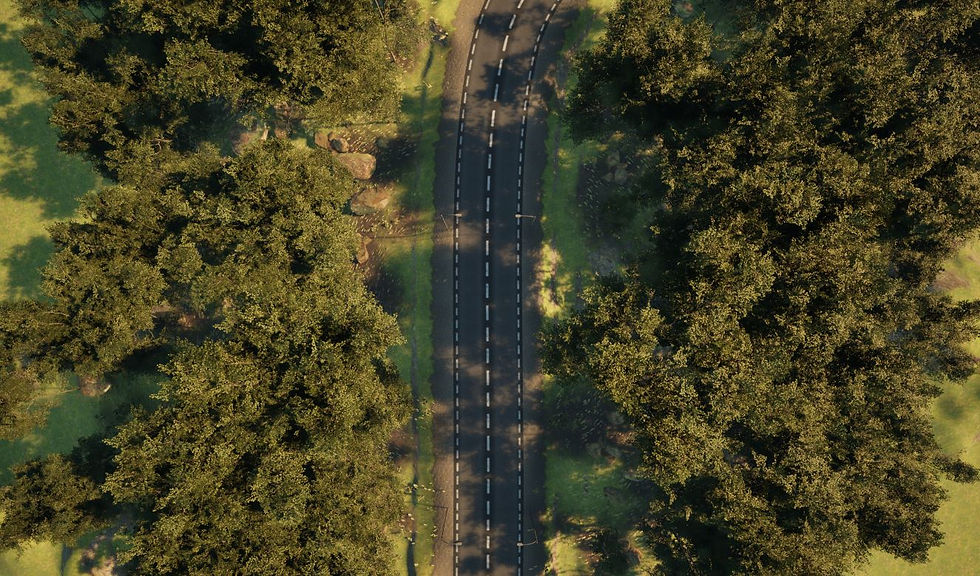
Landscape splines
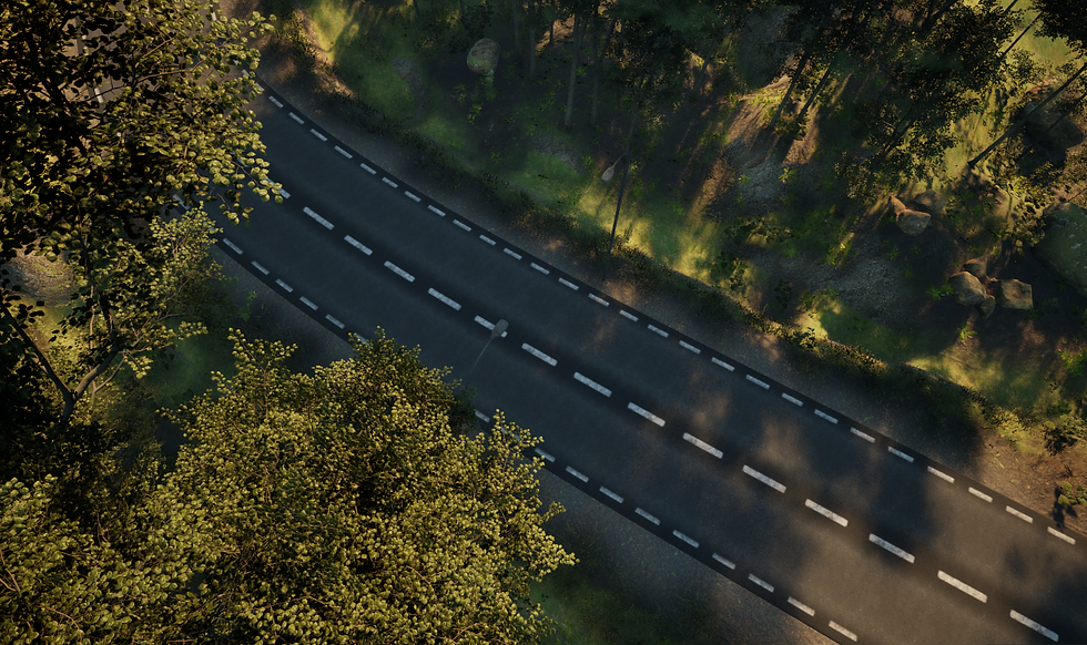
For roads I used Unreals built in landscape splines. This has many advantages compared to making your own road splines since it avoids clipping trough the ground and comes with a lot of useful built in functionality. The first advantage is that it automatically displaces the landscape to make the surface flat along the spline at the height you place the spline on. You can easily adjust the width and falloff of the road.
When moving your spline it will non-destructively move the landscape displacement with it. Secondly you can assign it a spline mesh (preferably some kind of road mesh) that follows the spline without any additional blueprinting. If you want to you can you can even put a landscape material on the layer of the road which will show underneath the spline mesh and on the sides, useful if you want some gravel beside the road. For a quick introduction on how to create and access landscape splines I recommend this video.
An important thing to consider when using landscape splines together with PCG is that the landscape spline will not be accessible to the graph unless your level has world partitioning enabled. You can convert your level to a level with world partitioning by going to (in the editor) Tools>Convert Level... it will then create a copy of your level with world partitioning enabled in the folder you specify.
To access the landscape spline inside the pcg graph create a get spline data node. In its details set Actor filter to All world actors, Actor selection to by class, and Actor selection class to LandscapeSplineActor. You can also select the landscape spline actor in the outliner and give it a tag in it's details panel to access it with it's tag instead. Accessing the spline makes it possible to filter out intersecting meshes and spawn content alongside the road such as streetlights and grass.
Ground
Here is where it starts to get a bit tricky since the PCG framework is not built to manipulate terrain or materials. There are some workarounds though.
The landscape patch plugin
I stumbled across this plugin in a YouTube video about manipulating terrain with pcg. It is however in still in beta. The way it works is that you use it to heighten or lower the terrain based on the position of a landscape height patch component. If you have an actor with the landscape height patch component and places that actor above the landscape, the landscape will automatically rise to the position of the component. If it is placed below ground level the terrain lowers at that point to the position of the component.
There are a few limitations though. First of all, the component is circular with only a radius and falloff value to control the impact it has on the landscape, secondly those values are not targetable within the blueprint graph as far as I know. So when is this plugin useful? Well, I used it in my scene to create trenches alongside a road. They didn't end up looking perfect, but it was the best solution I could find that was non-destructive and didn't involve any sculpting by hand.

Trench made with landscape height patch components.
To use it you have to spawn actors with landscape height patch components at the position where you want the ground to meet the component. In my case it was on either side of a spline I used for my road. You need to do this in a graph that is separate from your other graphs, otherwise there is a good chance you will get stuck in an infinite loop where the ground just keeps adjusting downwards or upwards.
In the details panel of the PCG component that instances the graph, go to Properties>Advanced>Generation trigger and set it to on demand then uncheck Regenerate PCG volume in editor. You the have to manually press cleanup then generate when you want to regenerate the graph. It is of course not a fully automated process, but it is way easier when iterating than doing all the work manually.
Landscape materials
To make a material for the ground that automatically recognizes slopes and changes depending on the steepness of the landscape I would recommend to make a landscape material which automatically blends your layers based on the landscapes shape. I found this tutorial very helpful. (Since the tutorial is in UE4 there is a node he uses (MatLayerBlend_Standard) that is obsolete, but I found a fix in the comments section about using the MatLayerBlend_StandardWithMaskEdgeTint node instead and modifying it by removing the tint input and using a vector 3 with a white color in its place)
You then assign this landscape material to your landscape and create a layer information asset for your material layer inside the landscape mode. Then fill the entire level with the material layer you just created.
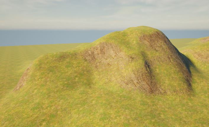
Example of auto blend between rock and grass.
Materials for (under) roads
I set up my road material layer in the same landscape material as I used for the automated blend for the entire rest of the landscape. For the road material layer I used alpha blend as blend mode instead of weighted blend, since the alpha blend can non-destructively be painted on top of another material layer.
I had big issues with make the road material layer display properly. It kept displaying as if it had really low opacity. The solution in the end for this was to set the main landscape material layer (the one with the automatic blend) to an opacity of something super low like 0,01. Doing this made both material layers display properly.
When creating a new material layer in the landscape mode, you must create a layer information asset for each material layer. To make the material layer I used for gravel on the sides of my road blend better with the underlying material layer I opened the layer information asset of the road material layer and used a noise texture to make the edges of the blend a bit more randomized and dynamic. I then used a PCG to generate some grass growing around the edges of the gravel to make the blend even less obvious.
Ground decals
In my forest I wanted to have at least partly another type of ground material, and I also wanted it to change and move with the bounds of my actor that holds the pcg generated forest. My solution for this was using decals than projects onto the ground inside the forest bounds. I am not sure how well this scales since it might cause a performance hit if you place too many decals in your level.

The brown ground material is made using decals.
To set this up you need to create a decal material. You do this by setting your material domain to deferred decal. Make sure you mask out the edges in a nice way so your decals won't be displaying as sharp squares on the ground (A sphere mask in combination with a noise texture did it nicely for me). The next thing you need to do is to create a decal actor where you assign your newly created decal material.

This is the shape I used for the decal opacity mask.
In your PCG graph you can now spawn these decal actors with the spawn actor node. Set Option to mergePCGonly in your spawn actor nodes settings. This seems to help the decal actors to regenerate when moving or changing the actor that holds the instance of the PCG graph. I recommend you to only spawn your decal actors on surfaces that are not too steep, removing points on steep surfaces with the normal to density node and a filter, otherwise the decal can appear stretched.
The next problem that needs to be dealt with is that your decals are now projecting not only on the ground, but also on other meshes in the area of the projection. I found a solution for this that works well even though it is a bit of work setting it up, and that is working with custom depth stencil layers.
First of all, go to your project settings and set Custom Depth-Stencil Pass to Enabled with Stencil.

In the details panel of your landscape, go to Rendering>advanced and enable Render CustomDepth Pass, then set CustomDepth Stencil Value to whatever layer number you wish to use for displaying the decals. In my case i used 5, but it shouldn't matter as long as you use another number for the content you want to exclude later on.
Go back to your decal material and make something like the following setup.
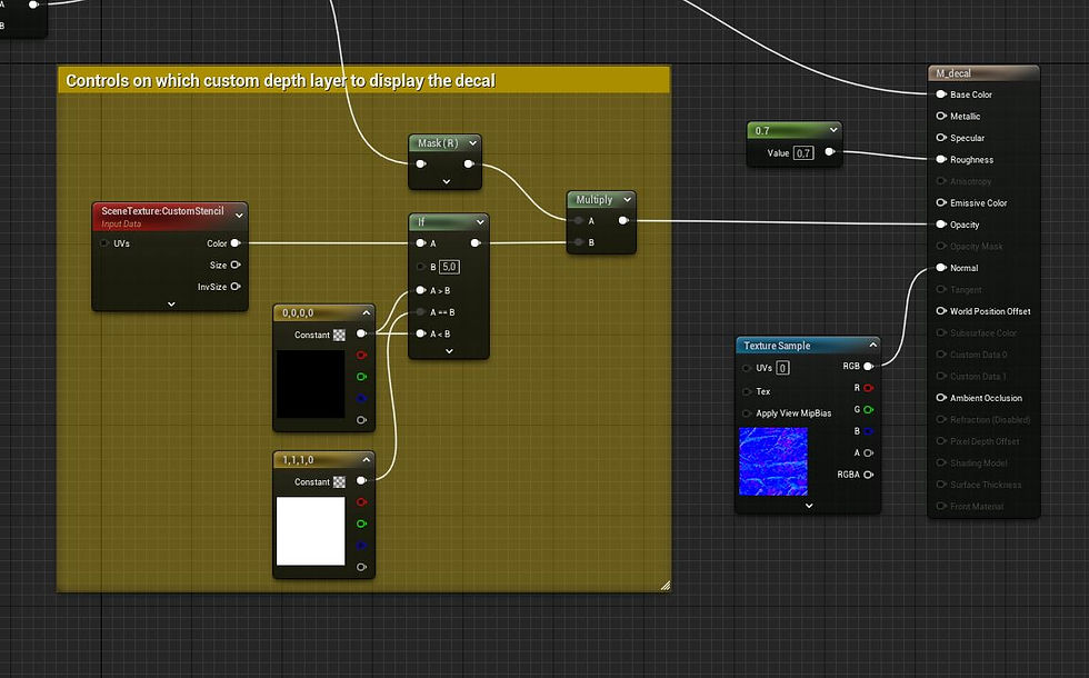
Here I compare the CustomStencil value from a scene texture node with the number I set as CustomDepth Stencil Value on my landscape. I then use my opacity mask and multiply it with a black or white vec4 making it opaque or transparent depending on if the input from the scene texture node matches my CustomDepth Stencil Value or not.
Now we need to specify what layer the things that shouldn't be hit by the decal projection should be on.
In your blueprint that ois instancing the graph through its PCG component or in another blueprint that references that one, make a function where you get all components of instanced static meshes and hlod instance static meshes. loop through all these and set render custom depth to true and set custom depth stencil value to another value than the one you used for your landscape.

This is how I made my function.
The last step is to make a custom pcg node that gets the actor that owns the function we just made (I used get actor(s) of class) and then calls the function. Place it in the end of the end of your node chain in the PCG graph. You create your custom nodes by creating a PCG Blueprint element in the content browser. I used a couple of select nodes to merge my node chain in the end before i plugged it in my custom node to ensure that there would be no bugs related to when the custom node executes.

The end of my pcg graph. RegenerateBlueprint is my custom node.

This is what the execute within context function of my RegenerateBlueprint node looks like. For more information about custom blueprints see my blog post called "building reusable tools with PCG".
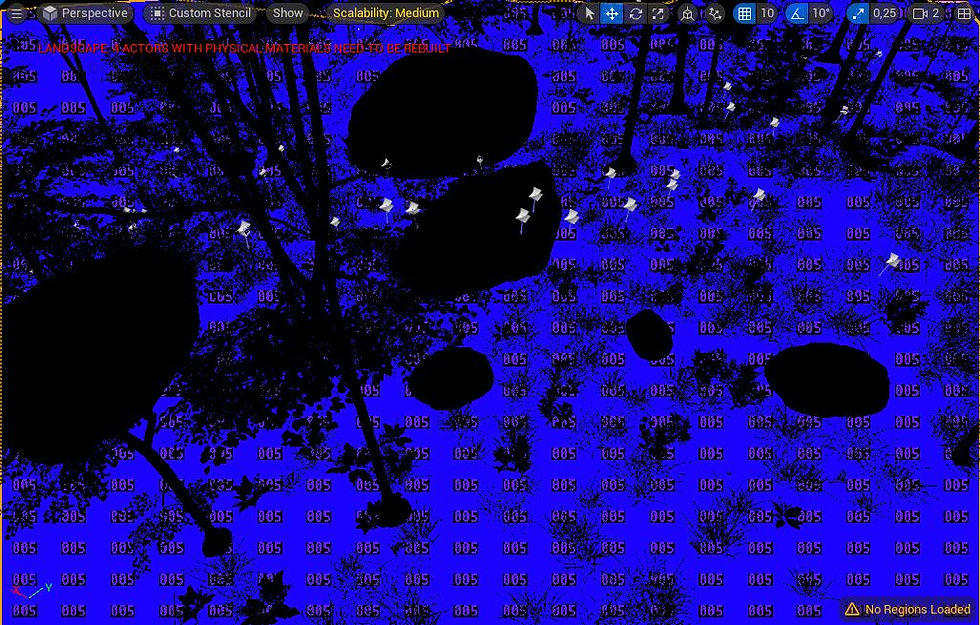
Use View mode>Buffer visualization> Custom stencil in the viewport to inspect your custom depth stencil layers if you need to debug.


Kommentarer