Creating reusable tools with PCG
- 4 dec. 2023
- 1 min läsning
Uppdaterat: 11 dec. 2023
To avoid repetitive work and make the most of the PCG graph you might want to build your graphs as a tools that can be reused and tweaked to fit several projects. From a technical artists perspective I focused on building something a designer could use to help them quickly create a level without ever having to enter the graph itself. This includes creating a a system of blueprints with exposed variables to control the pcg parameters, or using the built in parameters in the PCG graph.
I would recommend you to read the post called "Getting started with PCG" before reading this post.

Exposing parameters
There are a few different ways of exposing variables from the pcg graph to the user, enabling the user some control over the generation without entering the PCG graph.
Get actor property
get actor property is the node I find the most useful for building a user friendly system. This enables you to get a variable from either the parent actor or any other actor in your project. You specify the variable name In the Property name field in the details of the get actor property node. You need to make sure the variable is set to public inside the actor blueprint.
What I like about this technique is that the variables are easy to find for the user since they display in the actors details panel without having to go into any component of the actor, making it easy to get an overview of your different variables.

Variables exposed in the details panel of the actor.
Reamapping values for usability purposes
To make the user experience better I like to make two different variables when dealing with values in a specific range. For example, if I want the user to be able to give a value between 0,4 and 0,9 to control something inside the graph, it may be a bit confusing to the user what those numbers represents. I find it easier to use a variable with a range between 0 and 1 and then remap the value using a lerp node to get the value I want to pass on to the pcg graph.

Using a user exposed input between 0 and 1 to remap the value I pass on to the PCG graph.
The issue with this is that both variables needs to be public for the user to edit the value and the graph to be able to read the value we pass on. this means that the variable that in this case is called road distance remapped with a range from 0,4 to 0,9 is going to be exposed in the details panel as well. I tried to find a solution to avoid exposing this variable, and the closest I came was to go in to the details settings of the varibale and enable advanced display (located under the advanced tab). This puts the variable under an advanced tab that is closed by default in the details panel, making the variable less visible to the user.
Parameters
Opening the graph settings (located on the top bar inside the PCG graph) enables you to create your own parameters to use inside the graph. Under Instance>Parameters in the details panel you can click the plus symbol to add a parameter of any data type.
These parameters can be used inside the graph by writing "get [parameter name]" or by just searching for "parameters" in the search bar. These parameters will show up in the editor located under your pcg component that is instancing the graph.

TestBool added as a bool parameter to the graph.
Spawning meshes from variables
When setting what mesh you want to spawn with the static mesh spawner node from outside the graph, you must give the mesh as a soft object path (a path name that refers to the mesh object inside your content browser file structure). In the static mesh spawner node details you have to change Mesh selector type to PCGMeshSelectorByAttribute. You must create an attribute that holds the soft object path reference and add it to your points.
To do this you can use a get soft object path node in you actor blueprint graph and choose the mesh you want to spawn. Save the soft object path as a variable, then use a get actor property node in the PCG graph to get the soft object path. Plugging this value into an add attribute node in the attribute socket and plugging your points in the in socket will add the soft object path as an attribute under the name you specify as Output target on the add attribute node.

Adding the soft object path from the actor to the add attribute node.

Naming the Attribute in the Output Target field of the add attribute node.

Inspecting the points to see that the Attribute has been added correctly.
As Attribute name in the Static Mesh Spawner you give the name of the attribute that hold the soft object path (in this case MeshReference). I will highlight ways of creating this attribute allowing you to reference several different meshes in the custom nodes section of this post.
Custom nodes
Creating custom nodes to use in your PCG graph opens up for a lot more possiblities within the PCG framwork. The base of it all is the PCG Blueprint Element class that let's you create a custom PCG node using blueprinting.
PCG Blueprint Elements
To create a custom node for the PCG graph you must create a PCG blueprint element in your content browser. Opening this blueprint will bring you to something that looks very similar to the blueprint graph of blueprint actors. There are a few differences, mainly since this graph comes with a list of functions you can override to make our custom code for the node.

When hovering over the functions tab you will get a dropdown that says override. It lets you choose which functions you want to override. The only ones you need to know about to get started are the following functions: ExecuteWithinContext, point loop body and NodeTitleOverride.
Node title override
Node title override is the most straight forward function. It lets you set a display name (the name that the node will display in the PCG graph). Just type the name in the Return value field.

Execute within context
The ExecuteWithinContext and Points loop function are usually a bit more tricky. You can make a very simple function with execute within context, for example calling a function from an actor by just connecting the input socket to the output and execute some simple code in-between like you would in a normal blueprint. (see my example in decals section of the post called creating non destructive landscapes with PCG).
It's when you want to affect the points and their attributes that things start to become tricky. Basically there's a lot of boilerplate code connected to unpacking and packing the point data which needs to be done in order to access and manipulate the point data.
Boilerplate
My main source for the boilerplate is this video. It shows you one way of assigning meshes to your points by creating a custom node but also walks you through how to set up the boilerplate for the execute blueprint from context function as well as the point loop body. My code is stripped down to only contain the boilerplate as well as indication how to set up a custom attribute and add it to each point.

Execute within context. (click to expand)

continuation of the node chain.

Point loop body (click to expand)
These Pdf documents contains the boilerplate in text format. Copy and paste the text into your node editor inside the functions (this will create the nodes for you). You have to plug some values in manually to the output and input (refer to the images) and might need to create the context variable and spatial data variable as shown in the first picture. The nodes in the red comment sections are nodes you can change to whatever attribute you want. They are just there to show you where to create your custom functionality.
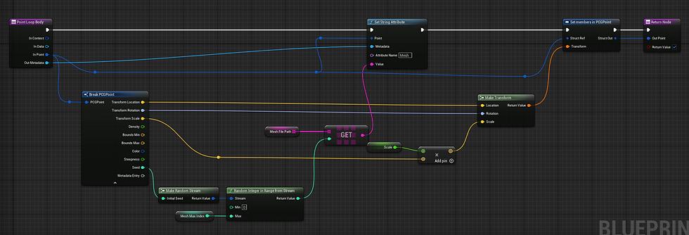
Point loop body
The point loop body loops through the the points. Here you can change values for the points attributes in a more unrestricted and direct way than you can inside the PCG graph. For example you can assign a different soft object path to each point instead of them all getting the same soft object path. One thing I used the point loop body for was to assign different meshes depending on what density value the points had (Together with a spatial noise node this made meshes of the same sort spawn in groups. I used it to make plants of the same sort spawn close to each other).
Spawning several different meshes using soft object paths
I want to recommend this video (it builds on the code from the video I recommended for the boilerplate section). I used it to create the base of my mesh spawning system but modified it to create a solution that worked better in my project.
In my case I created a blueprint actor that works as a master blueprint for the landscape creation. In this blueprint I set up a an array of structs where each struct holds an array of meshes and a name for the mesh set.

The struct array holding names and arrays of meshes in the master blueprint.
On my actor that spawns forests with help of a pcg graph I created a variable where I can give the name of a mesh set. This name is then compared with the mesh set name from the master blueprint and used to access the mesh array corresponding to it. This way I do not have to redefine the mesh arrays for every instance of my forest blueprint, and can change what meshes my forest spawns by just changing the name of the mesh set. I can for example have one set with beeches and one with pines defined in the master blueprint, and easily change what kind of trees my forest will spawn by inputting the name of the mesh set I want to spawn in an exposed variable.
Forest and GroundCoverage_1 is both names of mesh sets defined in the master blueprint.

Getting the mesh set name from the actors variable and inputting it to my custom node.

Inside the execute within context function.

Inside the get mesh set from other actor function (where the mesh set name variable is plugged in)
Inside the point loop body.
Execute blueprint
To execute your custom nodes you can access them in the PCG graph by adding an execute blueprint node in the PCG graph. Choose your PCG blueprint element in the Blueprint element type dropdown.
Generating from another blueprint
Sometimes you have a system where you want to control several graphs trough a central blueprint. In these cases it coul be good to use the Generate node to update these graphs when making a change in the central blueprint. Simply get the actors using the graph you want to regenerate and get their pcg components. This is your target for the generate node. Check the force chekbox.

Kommentarer