Getting started with PCG
- 4 dec. 2023
- 1 min läsning
Uppdaterat: 11 dec. 2023
In this post I will give you some basic information and tips for getting started with the PCG framework in Unreal. I would recommend you to read the post called "Introduction to PCG" before reading this post.

Creating a graph and instancing it in the level
To create a PCG graph in Unreal Engine you first need to install the Procedural Content Generation Framework plugin.
To create your PCG graph, navigate to add > PCG > PCG graph.
Once created the graph can be added as an instance to the PCG component of a PCG volume or a blueprint actor. The PCG volume inherently has a PCG component attached to it. For a blueprint actor you must add a pcg component manually. Dragging and dropping a PCG graph asset in to the level instantly creates a PCG volume that references the graph. To execute the code inside the graph, click generate in the details of you PCG component.

Debugging
To see the impact of each node in the graph you have the ability to visually debug the result in the level viewport. To do so, first make sure there is an instance of the graph in your level that is active (generated), and that you have selected the correct instance of the graph in the top bar dropdown inside the graph. If no instance is selected there will be a text saying no debug object selected on the dropdown.

not debugging any graph.

Debugging selected graph.
To visually debug a node, select it and press D (however, be careful not to click on the node name when selecting it since it will cause you to rename the node and all of a sudden you will have a lot of nodes named D) The points will show as small cubes in the viewport by default. On each node under the Debug tab in the details you have the option to change the debug visuals to another mesh or size. Sometimes the points are displayed as very big or small, then it can be a nice option to change the scale method to absolute (or whichever mode fits the situation best) and set the point scale to some value that is good for the current situation.

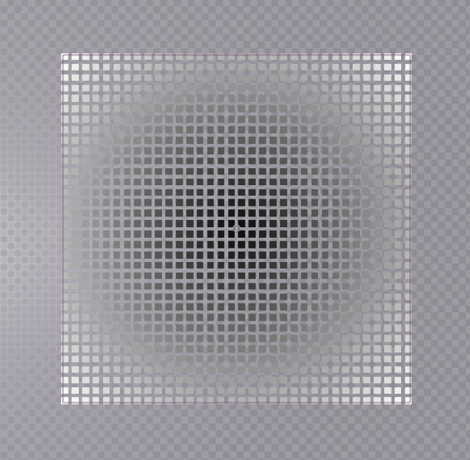
Visual debug of points with randomized density values.
You can debug several nodes at the same time, this can in some cases cause overlaps of points which will make the points appear glitchy. To disable debug on all nodes press alt+D. To stop debugging a single node click D again while having it selected.
To inspect all the attributes of a point, press A. This will make an indexed list of all points appear in the bottom part of your PCG graph. If your graph is not working as expected it can be a good idea to see that the your nodes actually has point data by using this kind of debug. When not getting a visual debug result when highlighting a node with D this is the first thing I do to troubleshoot, after checking that the selected graph to debug in the top bar is correct.

You can toggle between disabling and enabling a node by selecting it and pressing E. When a node is disabled the rest of the node chain will execute as usual bypassing the disabled node.
Sometimes the debugging is not working correctly. My main fixes for this is either regenerating the graph, reselecting the instance in the top bar dropdown, or simply disconnecting and reconnecting nodes in the beginning of the node chain.
Creating points
There are several ways of creating points, here are some example of common methods.
Sampling (getting data from external objects)
Under the sampler node category you will find different sampling nodes that creates points based on input from splines, surfaces, mesh or volumes. They are usually used together with a corresponding get [...] data node. For example the spline sampler is used together with a get spline data node as its input. The get [...] data nodes can select which actor it should use as target under Details>Settings>Actor Filter. One get [...] data node can go into several sampler nodes if you want to sample the same object in different ways.
When using Self as filter, the graph automatically detects objects of that type belonging to the same actor that the instance of the graph belongs to.
All world actors can be used to filter objects of a certain class or with a certain tag. This is useful to target objects outside the actor the pcg graph instance belongs to. If you cannot target the actor you wish to, try unchecking track actors only within bounds.
Sampling Splines
Spline sampling is one of the most used techniques when creating points. Under Details>Dimension of the spline sampler node you can choose to create points etiher on the spline, or if the spline is closed, on the interior of the spline (the area inside the closed spline). When creating points on a spline outside of a pcg volume, check the unbound box in the details. Checking treat spline as polyline on an interior spline makes straight connections between the spline points.
You can control how many points are spawned by setting distance increment or subdivisions per segment on splines depending on what mode you set, or change the interior spline sampling space on interior splines.
Sampling points on spline using distance as sample mode.
Sampling Mesh
To sample meshes with the mesh sampler node you must have the Procedural Content Generation Framework Geometry Script Interop plugin enabled. You do not need to get in data from another node, simply set the static mesh you want to sample in the details panel. The default location of the points is at the world origin. You can move them to other locations using for example the transform points or copy points nodes.When sampling a mesh you can choose different sampling methods. Either one point per triangle (a point in the middle of each triangle), one point per vertex, or poisson sampling (a more evenly distributed sampling). You can choose to voxelize the mesh which can give you more or less points depending on the value you give as voxel size.
Other sampling
There are other sampling methods such as volume sampling and surface sampling, working similarly to mesh sampling and spline sampling.
Other point creation methods
Create points
Lets you create one or more points. Check Local to make the positions relative to your pcg volume/bounds. To add several points at different positions, add entries to the position array and select FromPositionArray in the Point creation method dropdown. To create a single point set the method to FromSinglePoint (defaults position to 0,0,0) or FromSinglePosition to set a custom position for your point.
Create points grid
Creates points in a two or three dimensional grid. You can set grid extents to control the size of the grid and cell size to set the spacing of columns and rows. To make it Three dimensional check Volume. You can control which axes a two dimensional grid is placed on using the Coordinate Plane Axes dropdown.
Debugging point creation
In some cases you will have to check unbounded or uncheck cull points outside volume or Track actors only within bounds too get your points to display properly, depending on if you are using a PCG volume or a blueprint actor with a pcg component and at what locations those are placed in the world, along with what methods you are using for point creation.
Controlling point density and filtering points
Manipulating point density is one of the key practices inside the PCG graph. Changing the density value and filtering out points below or above a certain threshold value is a very easy way to separate points in to smaller sets which can be used to spawn different actors or meshes. For example, you may want all points with a density value over 0,5 to spawn a tree, points with a density between 0,2 and 0,5 to spawn a flower, and the points with a density below 0,2 not to spawn anything at all.
Filters
Density filter
This is probably the most straight forward node for filtering by density. Simply set a lower bound and an upper bound and it only passes through points with density values within those limits. There is also a checkbox option to inverse the filter.


before the filter node

After the filter node. The points with a density lower than 0,25 has been removed.
Point Filter
Works like Density filter but can also filter on other attributes. Check use constant threshold to set a float value as the threshold. You can specify which operator you want to use for the filtering in the details panel. This node has two output pins where it sorts out points inside and outside the specified threshold.
Point filter in range
This node is like a mix between the point filter and density filter. It takes a minimum and maximum threshold for the density (or other attribute) like the density filter, and it outputs the points in two different sets just like the point filter.
Controlling density values
There are many ways of manipulating density values. These are just a few examples of some techniques that are useful in multiple cases. A lot of these nodes is also useful to manipulate other attributes than density, but I will only talk about density for now since it is by far the most useful attribute.
Attribute noise
This node creates a generated high frequency spatial noise which is useful when you want to completely randomize the density on all points. It replaced a previous node called density noise.

Spatial noise
Creates a lower frequency spatial noise. You can control the contrast of the generated "noise texture" or play around with the scale to make the noise smaller or bigger, among other controls. This is useful when you want create groups of nearby points with similar density.

Distance
Sets a density gradient (0-1 value) from target to source point. Maximum distance controls the distance the target starts from. It is common to use points on a spline as target and points on the interior of the spline as source to change the density of points closer to the spline border (there is a similar function inside the spline sampler node called interior density falloff curve, the difference is that this way you get a constant max distance while the density falloff curve scales with the spline).
Normal to Density
Compares the points normal with a given normal (up (0,0,1) by default). Sets the density value higher the closer to the given normal the points normal is. It works very much like a dot product. Strength works as a threshold value, higher values includes more points , lower includes less This is useful for filtering away points on steep surfaces or placing geometry on top of other geometry (moss on rocks etc).

Maths node
The maths node contains different mathematical operators (multiply, add, subtract etc.). You must set what data it should be using in the details, (density, scale etc.). For example I could multiply the scale of a point by its density by plugging in the same set of points in both of the maths nodes inputs and select scale in the first input slot and density in the second.
When referring to attributes in the details panel, make sure to put a $ in front of the type as long as it is not a custom attribute created by you ($Density, $Scale etc.)
Blend modes
Sometimes you do not want to completely override (set) the density of your points but rather mix them with other density values. An example is a distance gradient where the inner parts of a spline has a high value and the parts closer to the border has a high value, but you might want to add a bit of a noise to add some variation. In those cases density blend modes comes in handy. Some nodes, for example the attribute noise node has the option to select which blend mode it should use (add, multiply etc.) which enables you to keep the base of your previous density while blending it with the new density values.
Spawning
Spawning meshes
To spawn meshes on your points, use a static mesh spawner node. This will spawn either HLOD instanced static meshes or Instanced static meshes on your points. The easiest way to spawn static meshes is by using the Mesh Selector type called PCGMeshSelectorWeighted . It is set as default when you create a static mesh spawner node.

debugging points used for spawning trees.
In he details panel there is a tab called mesh entries. Add Array elements with the plus icon, open the tab and the descriptor tab under the index you just created. Here you can define which mesh to spawn by picking a mesh in the static mesh slot. In the weight you can set the weight, meaning the likelihood of the mesh to be spawned compared to other meshes in the list.

I talk about how to spawn meshes by attribute in the post called "building reusable tools with PCG", enabling you to set up user exposed variables outside the PCG graph to decide what meshes to spawn.
Spawning actors
Spawning actors is done with the spawn actor node. Here you can define what actors you want to spawn in the Template actor class dropdown.
Other useful nodes and techniques
Difference
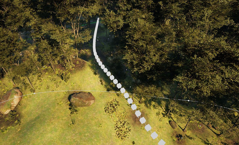
The difference node can be used to mask out points that intersect each other. For the exclusion method using Binary as Density function (this will exclude the points in the source input that are overlapped by points from the Differences ) the points that from the differences need to fully overlap the points from the sources input. This is overlap is decided by the bounds of the points. To make the bounds of the point bigger you can use a bounds modifier node and scale the points. This will not affect the scale of the points transform, only the bounds.

Road points (black) overlapping points from the forest.
Projection
The projection node projects points from the in socket onto the projection target. The projection target is usually a surface such as a landscape. This will make the points align to the height of the surface.
Subgraphs
Subgraphs are reusable PCG graphs. Any PCG graph can be a subgraph. Simply drag and drop a graph from your content browser in to your current PCG graph or use the subgraph node and select the graph you want to use in the details panel.

Kommentarer